As much as I admire Takahashi for their dedication to quality products, some of their design choices can be frustrating. Worse, the cost to accomplish even standard tasks with their equipment — connecting a camera to a scope, controlling a mount, etc. — are steep. I recently acquired an EM-200 Temma 2 mount, and before I could autoguide it or connect it to my computer, I had to overcome the non-standard cabling.
While the rest of the world has standardized their autoguiding connections with the same RJ-12 cable and jack (though not always the same pinouts) as SBIG’s now-ancient ST4, Tak for some reason decided to go their own way. The Tak connection on the Temma 2 is known as a mini-DIN-6. A quick search on the internet revealed that this is the same connection used on the old PS/2 keyboard and mouse cables. I had some of those laying around the house, so I my plan was to use one of those. Alas, this was not to be, as you’ll see in a minute.
Communicating with your mount on a deeper level than “speed up” and “slow down” usually requires what’s known as a serial port. Serial ports on mounts are a little less standardized. No modern computer has a direct serial (also loosely known as RS-232) connection, so you typically need a USB-to-serial adapter. The output of this is what’s known as a DB9 connector, which you then have to adapt to whatever your mount requires. For the EM-200, it’s a mini-DIN-4 connection. Again, a little internet research reveals that mini-DIN-4 is also the standard for S-Video cables. Aha, I have one of those lying around too!
Which brings us to an important point: you cannot use S-Video or mouse/keyboard cables for these connections. Why? The pins on the connector do not always reflect the wires in the cable. S-Video cables have two pins tied common, since the standard has two pins serving as ground. Thus, there are only three wires in the cable, and we four separate wires for four separate pins. It’s a similar story with the mouse cables: only four of the six wires are used. (Perhaps all six are used for PS/2 type keyboards? I only had a mouse on hand.) In fact, the DB9 serial cable I had actually turned out to only be connecting four of the pins when I opened it up.
So I needed one cable for autoguiding that was: RJ-12 Socket <———->mini-DIN-6
I also needed a cable for serial communications that was: USB<———->DB9<———–>mini-DIN-4
So it’s off to DigiKey to order some parts, since mini-DIN connectors are not something Radio Shack stocks in store. I ordered:
- 839-1091-ND “CBL ASSY MINI DIN MALE R/A 4POS”
- 839-1093-ND “CBL ASSY MINI DIN MALE R/A 6POS”
The DB9 connector I did have around the house (from Radio Shack, and commonly available). I also ordered a USB-to-serial adapter from ebay that has the FTDI chipset, as I heard that is the best choice, and I got an RJ-12 jack from Home Depot for $1.99 that has convenient punch-down connections on the back. Finally, I bought a project box from Radio Shack to house it all.
Thankfully, Takahashi has published the pinouts for their cables, so this was a straightforward project. I’ve reorganized them here in table format with schematics of the connectors.
The autoguide cable


The serial cable
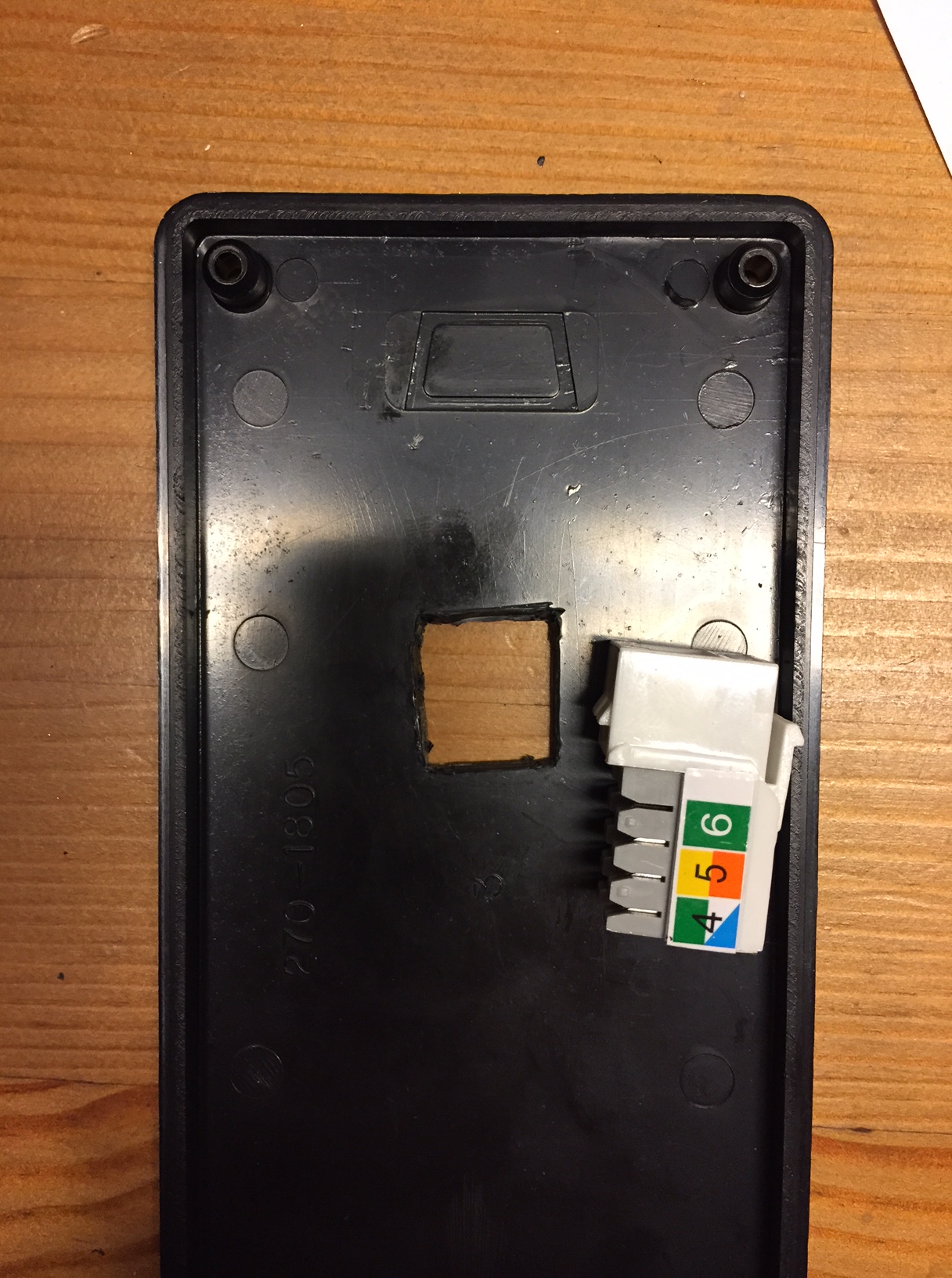
Now there is only the matter of assembling it all. These steps look easy, but it’s fairly tedious and can take a couple of hours. First, cut a hole in the project box to fit the RJ-12 socket:
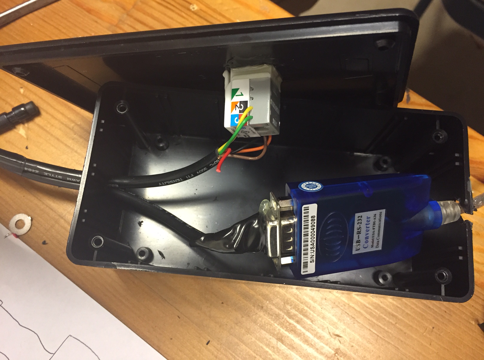
Now cut holes in the box to accommodate the cables (provide strain relief via knots or glue if needed), and strip the ends of each wire:

Using the tables above, solder the wires to each connector as appropriate. Double check the connections with a multimeter. Epoxy the RJ-12 jack to the box lid:
The final adapter box has a USB cable coming from one end, and the autoguiding and serial connections coming out the other:

And here it is attached to the tripod, ready for use:

